Turn on suggestions
Auto-suggest helps you quickly narrow down your search results by suggesting possible matches as you type.
Showing results for
- Good Sam Community
- Everything RV
- Technical Issues
- Epever 40 amp mppt delivered
Options
- Subscribe to RSS Feed
- Mark Topic as New
- Mark Topic as Read
- Float this Topic for Current User
- Bookmark
- Subscribe
- Mute
- Printer Friendly Page
Epever 40 amp mppt delivered
Options
- Mark as New
- Bookmark
- Subscribe
- Mute
- Subscribe to RSS Feed
- Permalink
- Report Inappropriate Content
Jan-02-2018 05:27 PM
Well From those that responded to my thread here,
https://forums.goodsamclub.com/index.cfm/fuseaction/thread/tid/29509210.cfm
I will start new for the review when I get it installed..But its going to be -3f here in NJ this weekend, and im old... I dont like the cold...ha ha..
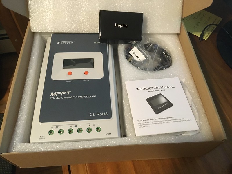
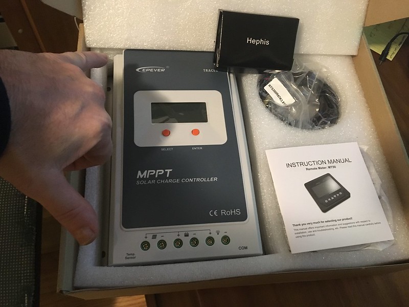
I have to say it was cheap 169$ delivered through amazon US delivery.. And i am posting becuase of the impressive packaging.
Ill get it installed as soon as I can and get some data to post how it operates with two 280watt panels...
https://forums.goodsamclub.com/index.cfm/fuseaction/thread/tid/29509210.cfm
I will start new for the review when I get it installed..But its going to be -3f here in NJ this weekend, and im old... I dont like the cold...ha ha..
I have to say it was cheap 169$ delivered through amazon US delivery.. And i am posting becuase of the impressive packaging.
Ill get it installed as soon as I can and get some data to post how it operates with two 280watt panels...
Mike L ... N.J.
2006 Silverado ext cab long bed. 3:42 rear. LM7 5.3 motor. 300 hp 350 ft lbs torgue @ 4000 rpms
2018 coachmen Catalina sbx 261bh
2006 Silverado ext cab long bed. 3:42 rear. LM7 5.3 motor. 300 hp 350 ft lbs torgue @ 4000 rpms
2018 coachmen Catalina sbx 261bh
46 REPLIES 46
Options
- Mark as New
- Bookmark
- Subscribe
- Mute
- Subscribe to RSS Feed
- Permalink
- Report Inappropriate Content
Jan-31-2018 05:04 PM
there is a reason for stick house solar positive ground
the earth is 'positive charge' during an electrical thunder storm
the sky is 'negative charge'
this why they use a positive for common and ground it out to earth ground
while it appears that lighting strikes down from the sky
the spark actually jumps up from the earth to sky
it is invisible until it meets the sky
then the ionization trail travels the reverse course lighting up the sky
making it appear that bolts strike down
this is all non-relevant in an RV situation, where the positive common (of the solar) is NOT bonded to rv frame ground
using the word 'ground' in an rv solar install, confuses the issue
as everybody thinks of RV/vehicle ground as the frame which is bonded to the battery negative
I can explain it to you.
But I Can Not understand it for you !
....
Connected using T-Mobile Home internet and Visible Phone service
1997 F53 Bounder 36s
But I Can Not understand it for you !
....
Connected using T-Mobile Home internet and Visible Phone service
1997 F53 Bounder 36s
Options
- Mark as New
- Bookmark
- Subscribe
- Mute
- Subscribe to RSS Feed
- Permalink
- Report Inappropriate Content
Jan-31-2018 03:22 PM
The Tracer manual says, "The Tracer-A series is a positive ground controller. Any positive connection of solar, load or battery can be earth grounded as required."
Earth grounded is not what happens in an RV installation.
My old PWM controller manual has " a common positive ground" and the diagram on page 6 here shows to "ground" the positive battery post if you do. In fact, I had the usual battery negative "ground" to the RV frame and the controller's output to battery pos and neg as usual, and it all worked no problem. (I had the plain version not the R one , but all same really)
http://www.epsolarpv.com/en/uploads/news/201310/1382336207652695.pdf
1. 1991 Oakland 28DB Class C
on Ford E350-460-7.5 Gas EFI
Photo in Profile
2. 1991 Bighorn 9.5ft Truck Camper on 2003 Chev 2500HD 6.0 Gas
See Profile for Electronic set-ups for 1. and 2.
on Ford E350-460-7.5 Gas EFI
Photo in Profile
2. 1991 Bighorn 9.5ft Truck Camper on 2003 Chev 2500HD 6.0 Gas
See Profile for Electronic set-ups for 1. and 2.
Options
- Mark as New
- Bookmark
- Subscribe
- Mute
- Subscribe to RSS Feed
- Permalink
- Report Inappropriate Content
Jan-31-2018 03:07 PM
mike-s wrote:MrWizard wrote:Which are exactly the same thing. In electrical circuits, "ground" is the common reference point. For controllers which tie all the positive terminals together, that's a positive ground. RVs which tie devices to a frame connected to battery -, that's negative ground. The two don't work well together, which is the whole problem.
here we go again
its NOT positive ground
it IS positive COMMON
NO by that description
a positive buss bar with batteries and solar controller and converter
would be called ground
and it is NOT
I can explain it to you.
But I Can Not understand it for you !
....
Connected using T-Mobile Home internet and Visible Phone service
1997 F53 Bounder 36s
But I Can Not understand it for you !
....
Connected using T-Mobile Home internet and Visible Phone service
1997 F53 Bounder 36s
Options
- Mark as New
- Bookmark
- Subscribe
- Mute
- Subscribe to RSS Feed
- Permalink
- Report Inappropriate Content
Jan-31-2018 03:34 AM
use the load terminals for timed circuits like designed, infinite timed combinations. I like on at dusk for 3hrs with dusk defined @7v, one or 2 1w led landscape lights let you see in the dark!
Options
- Mark as New
- Bookmark
- Subscribe
- Mute
- Subscribe to RSS Feed
- Permalink
- Report Inappropriate Content
Jan-30-2018 06:47 PM
BFL13 wrote:You could cut it short and admit you don't understand electrical circuits. But no, you want to dig the hole deeper. No one said the mismatch couldn't be made to work if you don't try using the load control circuit with negative grounded equipment. The saving grace is that the panels themselves are typically not connected to frame ground in the power circuit. You're kludging it by ignoring the built-in load monitoring of the controller and buying an external Trimetric monitor instead.mike-s wrote:MrWizard wrote:Which are exactly the same thing. In electrical circuits, "ground" is the common reference point. For controllers which tie all the positive terminals together, that's a positive ground. RVs which tie devices to a frame connected to battery -, that's negative ground. The two don't work well together, which is the whole problem.
here we go again
its NOT positive ground
it IS positive COMMON
Nope. I have had a number of different solar controllers, some of which have said in their manuals that they have a "positive ground".
Every one of them worked just fine in the RV whether pos or neg ground internally. Every one had its neg to the Trimetric shunt neg and all was good.
But, it's still wrong to claim, as you have, that there's a difference between "ground" and "common" for RV circuits. In household AC circuits, the difference is in which wires carry current and which are protective. For RV DC circuits, they're the same, there is no separation between ground and neutral.
Options
- Mark as New
- Bookmark
- Subscribe
- Mute
- Subscribe to RSS Feed
- Permalink
- Report Inappropriate Content
Jan-30-2018 06:11 PM
mike-s wrote:MrWizard wrote:Which are exactly the same thing. In electrical circuits, "ground" is the common reference point. For controllers which tie all the positive terminals together, that's a positive ground. RVs which tie devices to a frame connected to battery -, that's negative ground. The two don't work well together, which is the whole problem.
here we go again
its NOT positive ground
it IS positive COMMON
Nope. I have had a number of different solar controllers, some of which have said in their manuals that they have a "positive ground".
Every one of them worked just fine in the RV whether pos or neg ground internally. Every one had its neg to the Trimetric shunt neg and all was good.
1. 1991 Oakland 28DB Class C
on Ford E350-460-7.5 Gas EFI
Photo in Profile
2. 1991 Bighorn 9.5ft Truck Camper on 2003 Chev 2500HD 6.0 Gas
See Profile for Electronic set-ups for 1. and 2.
on Ford E350-460-7.5 Gas EFI
Photo in Profile
2. 1991 Bighorn 9.5ft Truck Camper on 2003 Chev 2500HD 6.0 Gas
See Profile for Electronic set-ups for 1. and 2.
Options
- Mark as New
- Bookmark
- Subscribe
- Mute
- Subscribe to RSS Feed
- Permalink
- Report Inappropriate Content
Jan-30-2018 05:50 PM
MrWizard wrote:Which are exactly the same thing. In electrical circuits, "ground" is the common reference point. For controllers which tie all the positive terminals together, that's a positive ground. RVs which tie devices to a frame connected to battery -, that's negative ground. The two don't work well together, which is the whole problem.
here we go again
its NOT positive ground
it IS positive COMMON
Options
- Mark as New
- Bookmark
- Subscribe
- Mute
- Subscribe to RSS Feed
- Permalink
- Report Inappropriate Content
Jan-30-2018 02:33 PM
I put my Tracer neg output to the Trimetric shunt same as with the other negs. The Trimetric AH counter needs that to get the totals right.
I doesn't matter if the controller is "positive grounded" since you do not "ground" the panels on the RV frame, and you do not "ground" the controller to the RV frame. It is an RV not a stick house.
I doesn't matter if the controller is "positive grounded" since you do not "ground" the panels on the RV frame, and you do not "ground" the controller to the RV frame. It is an RV not a stick house.
1. 1991 Oakland 28DB Class C
on Ford E350-460-7.5 Gas EFI
Photo in Profile
2. 1991 Bighorn 9.5ft Truck Camper on 2003 Chev 2500HD 6.0 Gas
See Profile for Electronic set-ups for 1. and 2.
on Ford E350-460-7.5 Gas EFI
Photo in Profile
2. 1991 Bighorn 9.5ft Truck Camper on 2003 Chev 2500HD 6.0 Gas
See Profile for Electronic set-ups for 1. and 2.
Options
- Mark as New
- Bookmark
- Subscribe
- Mute
- Subscribe to RSS Feed
- Permalink
- Report Inappropriate Content
Jan-30-2018 01:01 PM
here we go again
its NOT positive ground
it IS positive COMMON
meaning the panel positive, battery positive, load positive
are connected in the controller
charge control is done by switching the Negative side, load on/off is done by switching the Negative
you are not going the short positive and negative, no matter what you do with the shunt
you can probably put the shut in the positive cable if you wish
just reverse the (2) connections for senseing so it counts in the right direction
in many cases with many instruments, shunts do not have to go in the negative, external shunts can go in either line in most cases
convention has been to put them in negative / ground side
I can explain it to you.
But I Can Not understand it for you !
....
Connected using T-Mobile Home internet and Visible Phone service
1997 F53 Bounder 36s
But I Can Not understand it for you !
....
Connected using T-Mobile Home internet and Visible Phone service
1997 F53 Bounder 36s
Options
- Mark as New
- Bookmark
- Subscribe
- Mute
- Subscribe to RSS Feed
- Permalink
- Report Inappropriate Content
Jan-30-2018 12:18 PM
lawrosa wrote:
...
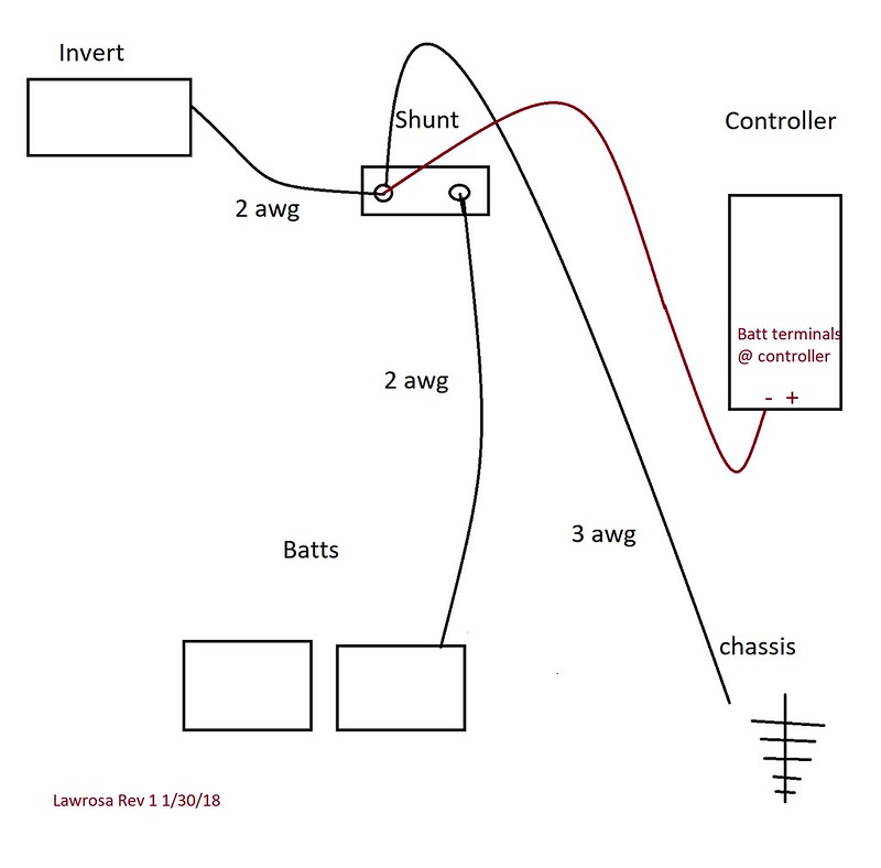
2. But then the question is the solar. Its a positive ground controller. So to run the solar to the shunt would mean I am tieing the solar neg to ground.
...
My understanding is that the pos ground only applies to the "load" terminals of the Epsolar Tracer
So your graph looks ok to me.
2014 ORV Timber Ridge 240RKS,8500#,1250# tongue,44K miles
690W Rooftop + 340W Portable Solar,4 GC2s,215Ah@24V
2016 Ram 2500 4x4 RgCab CTD,2507# payload,10.8 mpgUS tow
690W Rooftop + 340W Portable Solar,4 GC2s,215Ah@24V
2016 Ram 2500 4x4 RgCab CTD,2507# payload,10.8 mpgUS tow
Options
- Mark as New
- Bookmark
- Subscribe
- Mute
- Subscribe to RSS Feed
- Permalink
- Report Inappropriate Content
Jan-30-2018 12:13 PM
And I am not the smartest tool in the shed but in determining a amp meter my issue is
1. To do it right I assume all grounds go through a shunt. That means some rewireing. I can put the shunt between neg cable and ground but it would be outside RV on frame rail unless I do a bit of rewiring I can put it in the passthrough.
2. But then the question is the solar. Its a positive ground controller. So to run the solar to the shunt would mean I am tieing the solar neg to ground.
3. The way I see #2 above is I would possibly need two shunts to not have the solar grounded to frame. But then Can I assume the amp meter is able to read from two shunts? And will this set up still give me correct SOC?
4. The last delema is the inverters... Geeez That 2 gauge will all need to be rerouted also..
But then thinking about it maybe its a non issue...
I came up with this... Does this seem correct?
The charge controller wire is 6 gauge FYI..
Mike L ... N.J.
2006 Silverado ext cab long bed. 3:42 rear. LM7 5.3 motor. 300 hp 350 ft lbs torgue @ 4000 rpms
2018 coachmen Catalina sbx 261bh
2006 Silverado ext cab long bed. 3:42 rear. LM7 5.3 motor. 300 hp 350 ft lbs torgue @ 4000 rpms
2018 coachmen Catalina sbx 261bh
Options
- Mark as New
- Bookmark
- Subscribe
- Mute
- Subscribe to RSS Feed
- Permalink
- Report Inappropriate Content
Jan-29-2018 09:33 PM
Well its been nicer weather the past few days...
Ill get boondocking data when I can. I think I have the trailer set up how I want it for now...
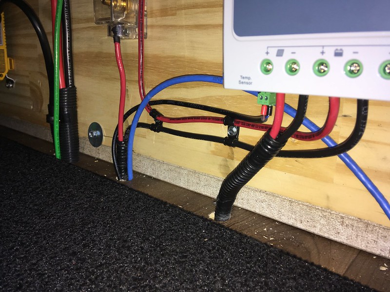
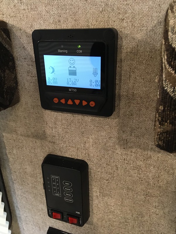
I ran the temp probe from the tracer to one battery and metal taped the sensor to it.. Kind of lower then mid point. Ill let you all know the temps down the road when im pumping amps into them...
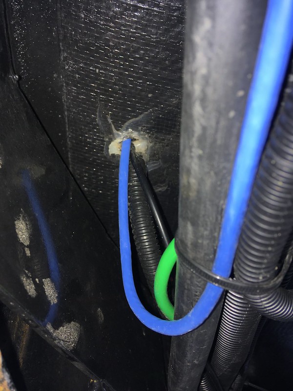
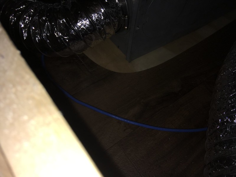
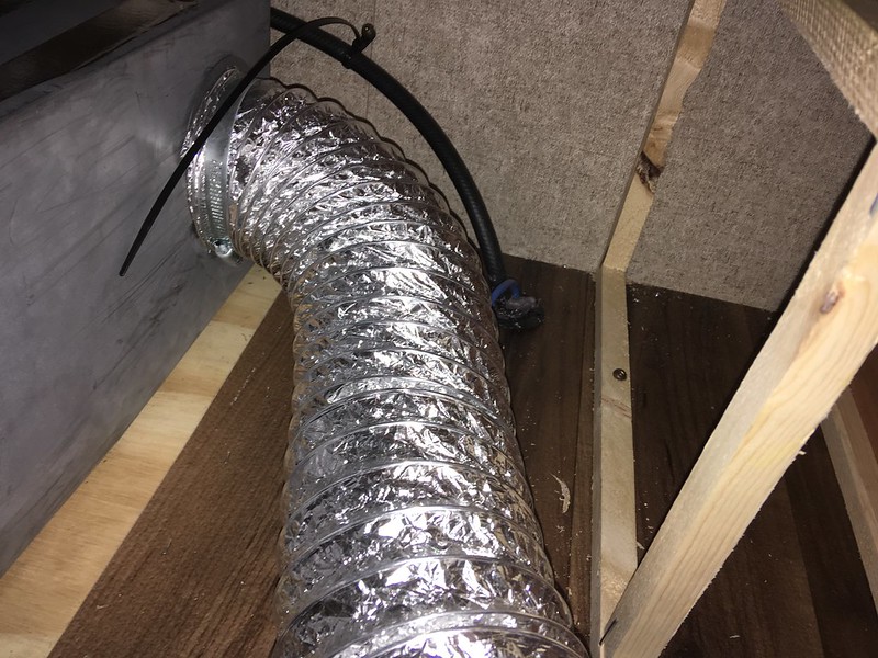
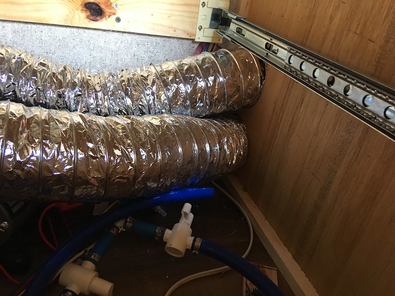
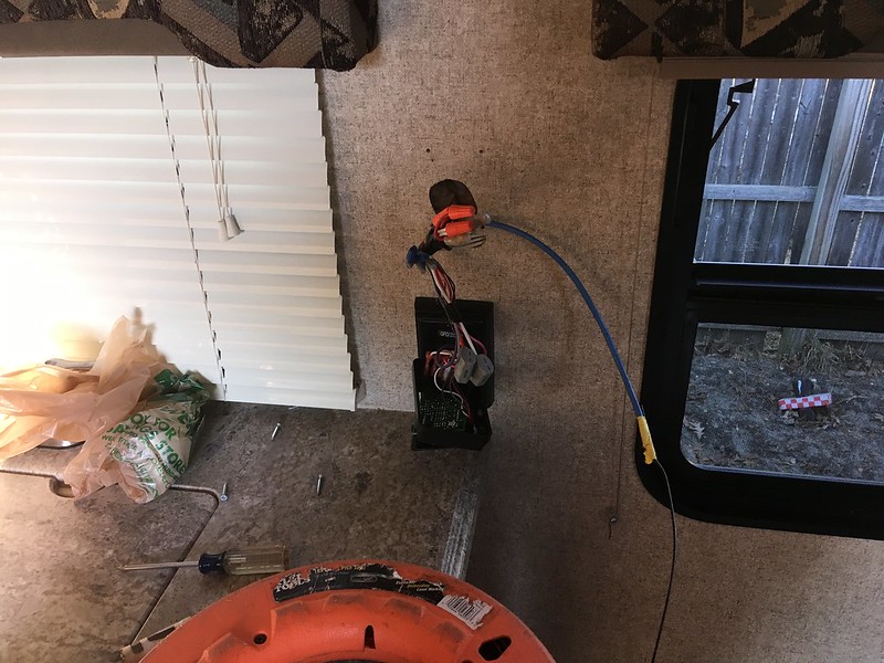
Also I ran rj45 cable from controller , through floor and under trailer. I then ran it up the propane bulkhead tube that comes up under the coach to furnace. Then through duct chase into kitchen sink/pump cabinet.
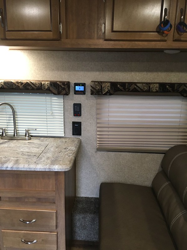
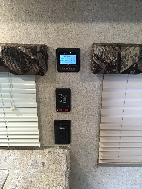
Then snaked it up the wall to where the monitor is. Cut a 3" hole and flush mounted the remote meter..
I think it came out OK..
Ill get boondocking data when I can. I think I have the trailer set up how I want it for now...
I ran the temp probe from the tracer to one battery and metal taped the sensor to it.. Kind of lower then mid point. Ill let you all know the temps down the road when im pumping amps into them...
Also I ran rj45 cable from controller , through floor and under trailer. I then ran it up the propane bulkhead tube that comes up under the coach to furnace. Then through duct chase into kitchen sink/pump cabinet.
Then snaked it up the wall to where the monitor is. Cut a 3" hole and flush mounted the remote meter..
I think it came out OK..
Mike L ... N.J.
2006 Silverado ext cab long bed. 3:42 rear. LM7 5.3 motor. 300 hp 350 ft lbs torgue @ 4000 rpms
2018 coachmen Catalina sbx 261bh
2006 Silverado ext cab long bed. 3:42 rear. LM7 5.3 motor. 300 hp 350 ft lbs torgue @ 4000 rpms
2018 coachmen Catalina sbx 261bh
Options
- Mark as New
- Bookmark
- Subscribe
- Mute
- Subscribe to RSS Feed
- Permalink
- Report Inappropriate Content
Jan-25-2018 07:52 AM
lawrosa wrote:
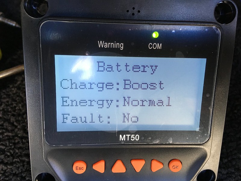
OK ran test today and all worked out good.
It went into boost... But I ran a load first then plugged the solar in... Ummm I think I read somewhere , maybe BFL had the issue of it not getting off of float and a simple on/off of the controller is a quick fix. I will not know the idiosyncrasies until I get out there boondocking..
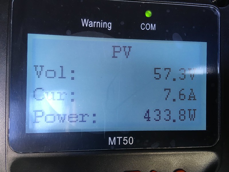
So two 280 watt panels serve this controller well. This was low low sun about 2pm here in NJ.
433 watts 57 volts not bad..
This is with a small load on just seeing what amps I could get a 2pm sun.
6 amps from panels. ( These are like 9 amp panels Highest I say was 7 amps this test run) But 31 amps to batts.. Wow.
Yup showing boost this time around. So I now know what to look for in regards to normal operation..
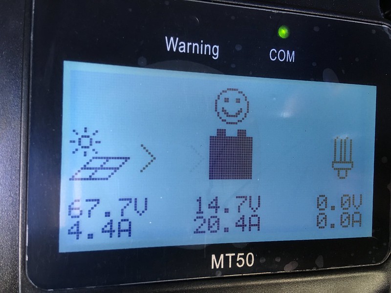
I would like to note when it when to boost mode with tapered amps as shown below, the volts were a bit flakey. I set the controller to 14.7 for my test. And when it reached that set point from bulk it started tapering.
But it was not a constant 14.7... It fluctuated. Went as high as 15 volts and down to say 14.2.. Back and forth several times.
I can see it going lower but cranking up to 15 volts IDK. I think there is a few sentences about this in the instructions. And that its time accumulative. Meaning even if I set it for 2 hours boost and the sun hides here and there, it will track that time and continue to try to boost for 3 hours. Weather it spent enough time there or not.
IDK... This Ill have to figure out in my camping adventures.
I still have some wire running of the remote meter to the kitchen area and run the temp probe maybe to the batteries.
Not sure if temp probe is needed or not. It defaults to 25c.
The only this is the temp probe may help keep the batts from over heating..
Says stops charging if batts get to 65c.. 150F? and if the controller gets to 85C... 200F?
Here is the start of amps taper...
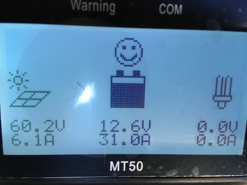
The 31 amps was controller output, not what batteries were accepting. You need a battery monitor to know what the batts were taking in. Subtract battery in amps from controller output amps, and that is your other loads being run by solar. Other loads get first grab at the controller output. Anything left over (if any) goes to battery.
You can see all that exciting action if you have a Trimetric as well as your controller's display. 🙂
On Float--once the controller drops to Float, it is still a buck converter. It just isn't doing MPPT anymore. (so it does PWM--your flakey voltages) It only does MPPT in Bulk. But no matter, if the load demand goes up, it will provide higher amps up to what the solar can do just then. Beyond that, the battery provides.
Eventually, the battery voltage will fall to where the controller will kick into Bulk and start doing MPPT again. If you don't want to wait, especially if the adjustable voltage for Float is capped lower than it is for Bulk (as it is with the Eco-W), then you could fool it by disconnecting the PV side and reconnecting. If battery voltage is low enough it will go to Bulk.
Normally while camping you will not want to be so busy playing with the solar in such detail, and it won't make much difference in how things go that day anyway. 🙂
1. 1991 Oakland 28DB Class C
on Ford E350-460-7.5 Gas EFI
Photo in Profile
2. 1991 Bighorn 9.5ft Truck Camper on 2003 Chev 2500HD 6.0 Gas
See Profile for Electronic set-ups for 1. and 2.
on Ford E350-460-7.5 Gas EFI
Photo in Profile
2. 1991 Bighorn 9.5ft Truck Camper on 2003 Chev 2500HD 6.0 Gas
See Profile for Electronic set-ups for 1. and 2.
Options
- Mark as New
- Bookmark
- Subscribe
- Mute
- Subscribe to RSS Feed
- Permalink
- Report Inappropriate Content
Jan-25-2018 07:02 AM
Nice sarcasm
Way off point, but i appreciate sarcasm
Adding that extra wire, in most class A, would not be worth the work
Just add another meter and be done with it
Way off point, but i appreciate sarcasm
Adding that extra wire, in most class A, would not be worth the work
Just add another meter and be done with it
mike-s wrote:MrWizard wrote:It's pretty simple, but since you don't know how: Disconnect the battery and converter connections from the load center. Those tie together and go to the battery connection on the solar controller. The load output of the controller goes to the load center - where the battery was previously connected.
since we RV, the RV power control fuse center would have to be wired to the controller
As for the rest, confirmation bias is a powerful thing.
I can explain it to you.
But I Can Not understand it for you !
....
Connected using T-Mobile Home internet and Visible Phone service
1997 F53 Bounder 36s
But I Can Not understand it for you !
....
Connected using T-Mobile Home internet and Visible Phone service
1997 F53 Bounder 36s
Related Content


